This month has seem some interruptions to normal proceedings as my wife and I got sick and our second Granddaughter has arrived - welcome Alice!
Apart from that, we have received the proof of concept Ambient Light Detector PCB's, planning has commenced on the Standard Signaling Module, and made some more progress on the Signaling Concept Design, Pierre had another training session and the final Grand Opening Video has been completed.
So once again, absolutely nothing was done in the layout room this month! I might have to change that next month as my medical plan says I should do more exercising - I think that all the movement working above & below the layout qualifies for that!.
Ambient Light Detector PCB
Last month I informed you that Wayne and I completed the design of the Printed Circuit Board and two proof of concept boards were ordered - They have arrived!Murphy is alive and well too - I realised that I had made a couple of errors in the circuit diagram which found its way onto the board but I am sure it will be easy to fix (very lucky!!). The current draw was quite a bit higher than I expected then I discovered that the 3.3V voltage regulator "was a radiator" as it was drawing 0.5A - we put it the wrong way round! The high current circuit check also revealed that I left out 10 current limiting resistors on signal lines (10 x 20mA = 0.2A - Ah that will make a big difference). The trimpot holes were one size too small too.
I was really impressed with the finish of the boards, which included solder masking, see below.
 |
| Board as received |
 |
| Board with components mounted |
Adding current limiting resistors
 |
| 10 x 330 Ohm between MSP Pins & Optocouplers |
 |
| Traces broken with Dremel & Stone bit |
3.3V regulator modifications

Previously I had always used Dave Loman's standalone implementation which uses a 10k Ohm resistor between Vcc & Pin 16 when battery powered.
 |
| Regulator installed the correct way round, 47k Ohm resistor and 2 x 10uF 50V Caps. |
Programing tweak
// If you're not using the 32kHz crystal then you need to clear the oscillator fault flag and take it out of crystal mode like so.
IFG1 &= ~OFIFG;
while (BCSCTL3 & LFXT1OF)
BCSCTL3 = LFXT1S_2;
while (BCSCTL3 & LFXT1OF)
BCSCTL3 = LFXT1S_2;
I do it right after
WDTCTL = WDTPW + WDTHOLD; // Stop WDT
We got 3 outa 4 right - duh....
So I id further mods to prove the rest works....
 |
 |
| Underside trace cuts and jumpers to what it should be... |
Final Test
Where to from here
Standard Signaling Module
Planning has commenced for the "backbone" module see below.

.jpg)
.jpg)
.jpg)
.jpg)
.jpg)
.jpg)
.jpg)
.jpg)
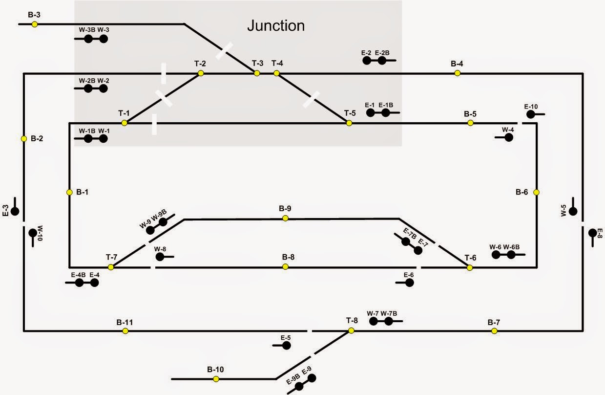
Signalling Concept Design
Last month I mounted the development board on a frame and had to revamp the "Junction Logic" board to isolate the 3.3V microprocessor circuit from the 12 V signal operation circuit.
I have refined the microprocessor programming to include "error checking" and undertaken extensive testing. I can report I think I have it working fairly reliably now.
 |
| Signal Trial |

Below are links to 3 videos, 2 that show the normal operation of the 4 blocks in each of the inner and outer loops of the pilot and the third shows the "Junction Routes".
Outer Loop (Top - East & West signals)
Inner Loop (Bottom - East & West signals)
Junction Routes (Top & Bottom, East & West signals)
Pierre in training
Pierre is gaining more confidence and I think he is enjoying the experience. He has completed a pick up run and a separate set out run. Now for the combination!! I have put a small presentation together for him to learn the different types of rolling stock.Well I can report that he decided that it was harder than expected and he needed some guidance! A "try again" has been requested however it has not happened as my wife & I have had the lurgy and been put on antibiotics and grounded by the Doc.
Grand Opening Video
Part 3 is now available.A BIG thank you must again go to Don for all the work required to put the 3 videos together for me.
That's it for this month.
Thanks again to those that continue to help me achieve my ambitions and hello once again to all my followers!
Till the end of November.
-ooOOOoo-


